Mold Design
Project-based mold design for plastic injection, aluminum injection, zinc injection, and volume mold making.
Mold Design
Project-based mold design for plastic injection, aluminum injection, zinc injection, and volume mold making.
- 01Plastic injection molds, aluminum injection molds, zamak injection molds and volume mold making can be evaluated on a project basis.
- 02Single-cavity, multi-cavity, hot runner, cold runner and insert mold configurations can be evaluated according to project requirements.
- 03Software such as Siemens NX, SolidWorks, Cimatron and Moldex3D can be used in the process.
- 04The mold design process can proceed through 3D design review, technical evaluation and revision steps.
- 3D CAD file
STEP, IGES, or native format (SolidWorks, NX)
- Material specification
Plastic type: PP, ABS, PA, POM, etc.
- Annual production volume
For mold steel selection and lifetime calculation
- Surface finish requirements
SPI finish class or custom texture request
- Special form requirements
Undercuts, threads, or side actions
- DFM analysis scope
Simulation and fill analysis expectations
Simulation in Mold Design
Flow analysis performed with Moldex3D can be used to evaluate plastic behavior inside the mold cavity during the design phase.
Filling process simulation can help identify potential issues such as sink marks, weld lines, and air traps before production begins.
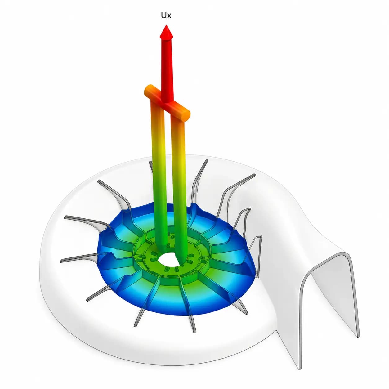
Moldex3D flow simulation — not an actual project output
Reverse Engineering
Creating manufacturable CAD models from physical parts or 3D scan data.
Plastic Injection Mold Manufacturing
Manufacturing plastic injection molds according to project and production requirements.
Product Development
Planning the product development process from idea, sketch, sample, or existing part to production-ready design.
Technical Consulting
Technical evaluation and improvement support for molds, production, materials, processes, and part design.
The female half of a plastic injection mold. It is the interior surface that shapes the molten plastic and defines the outer geometry of the part. Typically located in the stationary platen.
Read Definition →CoreThe male half of a mold. It forms the interior surfaces and hollow features of the part. Typically located in the moving platen and, together with the cavity, defines the full part geometry when closed.
Read Definition →DFM — Design for ManufacturabilityDesign for Manufacturability (DFM) is the analysis of a part's suitability for mold tooling and plastic injection processes during the design phase. Wall thickness uniformity, draft angles, and overall part geometry are the primary elements of this analysis.
Read Definition →Draft AngleA slight taper applied to vertical surfaces of plastic injection parts to allow clean ejection from the mold. Typical values range from 1° to 3°, though textured surfaces may require greater angles.
Read Definition →GateThe opening through which molten plastic passes from the runner system into the mold cavity. Gate size, location, and type (pin, tunnel, edge, etc.) directly affect fill quality and the formation of weld lines in the part.
Read Definition →Parting LineThe plane or surface where the two halves of the mold (cavity and core) separate. This line may leave a slight mark on the part; it is typically planned at an inconspicuous location or at a natural geometric boundary.
Read Definition →Sink MarkSurface depressions that form on plastic parts during cooling, caused by volumetric shrinkage in thicker cross-sections beneath the surface. Minimized by uniform wall thickness and optimized cooling channel design.
Read Definition →Weld LineThe line formed in a mold cavity where two molten plastic flow fronts coming from different directions meet. Mechanical strength and surface quality can be reduced at the junction; minimized through gate placement design.
Read Definition →Frequently Asked Questions
- What mold types are covered?
- Plastic injection, aluminum injection, zinc injection, and volume mold making can be evaluated on a project basis. Single-cavity, multi-cavity, hot runner, cold runner, and insert mold configurations are determined by project requirements.
- Is DFM analysis included in mold design?
- Yes. Manufacturability analysis (DFM) is an integral part of the process. Wall thickness distribution, draft angles, cooling channel layout, and gate positioning are all evaluated during the design phase.
- What CAD software is used?
- Siemens NX, SolidWorks, Cimatron, and Moldex3D may be used in the process. Output format is determined by project requirements.
- How does the mold design process work?
- The process typically includes 3D design review, technical evaluation, and revision stages. Mold manufacturing begins after design approval.
- Can existing molds be revised?
- Yes. Revision, improvement, and technical evaluation of existing molds can be arranged on a project basis.
Download the Design Guide
PDFA technical reference covering common design mistakes in plastic injection parts and their cost implications. Delivered as a PDF to your email.
Let's Evaluate Your Project Together
Share your technical requirements and we'll prepare a solution plan tailored for you.